
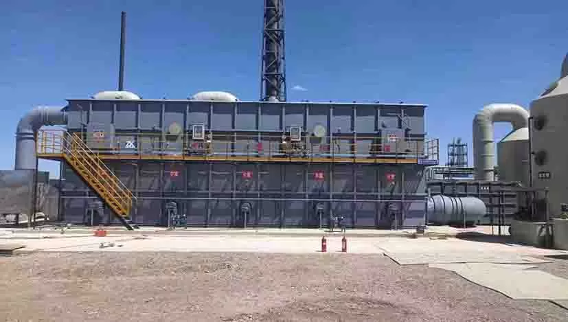
Regenerative Thermal Oxidizer (RTO)
Advanced thermal oxidation system for medium to high concentration organic waste gas treatment with 99%+ efficiency and 95%+ heat recovery
Key Features
Product Description
The Regenerative Thermal Oxidizer (RTO) is a highly efficient air pollution control technology designed for medium to high concentration organic waste gas treatment. The RTO system thermally oxidizes organic compounds (VOCs) in waste gas into corresponding carbon dioxide and water at high temperatures, thereby purifying the waste gas and recovering the heat released during waste gas decomposition. Three-chamber RTO achieves waste gas decomposition efficiency of over 99% and heat recovery efficiency of over 95%, featuring low operating costs and the ability to process large volumes of medium to low concentration waste gas.
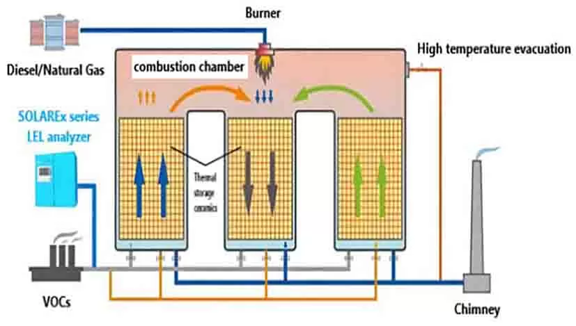
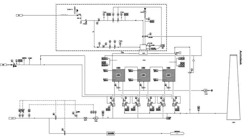
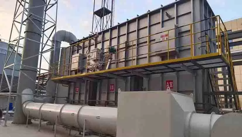
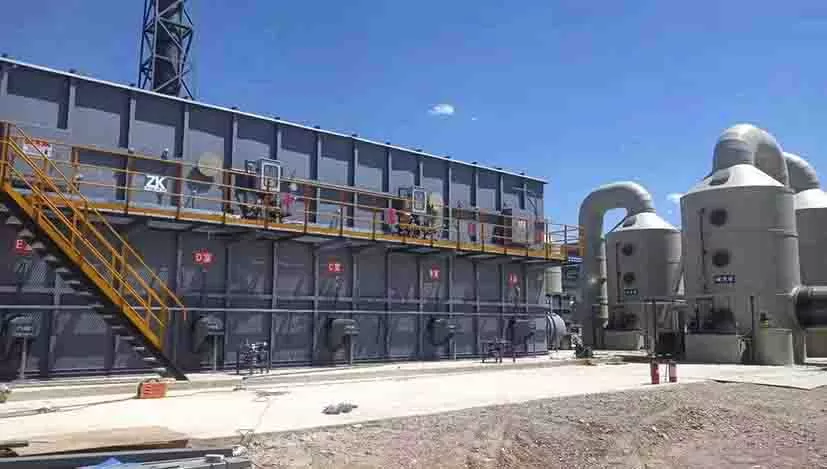
The RTO main structure consists of a combustion chamber, heat storage chambers, and switching valves. Different heat energy recovery methods and switching valve types are selected according to customer requirements. The principle involves heating organic waste gas to above 760°C, causing VOCs in the waste gas to oxidize and decompose into carbon dioxide and water. The high-temperature gas generated by oxidation flows through specially designed ceramic heat storage media, causing the ceramic to heat up and "store heat," which is then used to preheat subsequent incoming organic waste gas, thereby saving fuel consumption for waste gas heating.
Under suitable waste gas concentration conditions, the system can achieve self-sustaining operation without additional auxiliary fuel. When the waste gas concentration at the RTO inlet reaches a certain value, the heat released by VOCs combustion can maintain the energy reserves for RTO heat storage and release, allowing the RTO to maintain combustion chamber temperature without using fuel.
Working Principle & Process Flow
Three-Chamber Cyclic Operation
Phase 1: Waste gas passes through heat storage chamber A for preheating, then enters the combustion chamber for burning. Heat storage chamber C residual untreated waste gas is reverse-blown back to the combustion chamber for incineration (purge function). Decomposed waste gas exits through heat storage chamber B while heating chamber B.
Phase 2: Waste gas passes through heat storage chamber B for preheating, then enters the combustion chamber for burning. Heat storage chamber A residual untreated waste gas is reverse-blown back to the combustion chamber for incineration. Decomposed waste gas exits through heat storage chamber C while heating chamber C.
Phase 3: Waste gas passes through heat storage chamber C for preheating, then enters the combustion chamber for burning. Heat storage chamber B residual untreated waste gas is reverse-blown back to the combustion chamber for incineration. Decomposed waste gas exits through heat storage chamber A while heating chamber A.
This cyclic operation maintains the combustion chamber temperature at the set temperature (generally 800-850°C). The ceramic heat storage media should be divided into two or more zones or chambers, with each heat storage chamber sequentially experiencing heat storage, heat release, and purge procedures in continuous cycles. After the heat storage chamber "releases heat," a portion of treated clean exhaust gas should immediately be introduced to purge the heat storage chamber (to ensure VOC removal rate above 95%), and only after purging is complete can it enter the "heat storage" procedure.
Advanced Switching Valve Technology
Mechanical + Pneumatic Dual Sealing
Our company has developed an innovative dual sealing system for RTO switching valves based on actual operating conditions, combining mechanical and pneumatic sealing technologies.
Strong Anti-Pollution
Pneumatic sealing prevents liquids, grease, and impurities from entering the sealing interface, reducing wear from chemical and physical reactions.
Extended Lifespan
Reduces physical fatigue from continuous contact and collision, preventing valve deformation and leakage even without chemical reactions.
High Safety
Eliminates mechanical wear caused by high temperature, contact fatigue, and chemical reactions, ensuring reliable safety performance.
Switching Valve Performance
Advantages
Applications
Industries
Treatable Organic Compounds
Technical Specifications
Performance Parameters
Design Parameters
Detailed Technical Data
| System Pretreatment | None required |
| Material Options | Q235/304/2205/2507 (based on waste gas composition) |
| Safety Measures | Fire damper/Flame arrestor/High temp relief valve/RTO explosion relief/High temp alarm cutoff |
| Fire Protection | RTO inlet flame arrestor/Inlet duct fire damper |
| Explosion Relief Design | High temp relief valve/RTO explosion relief device |
| SIS Safety System | Monitors hazards, provides warnings, executes predetermined procedures to prevent accidents |
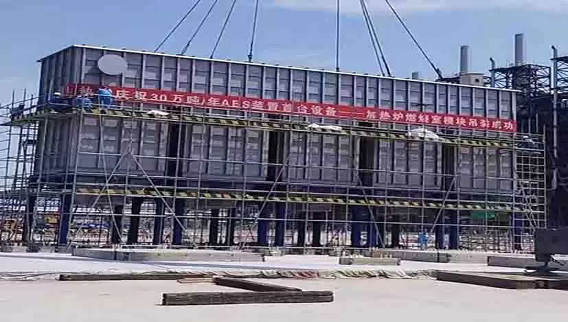
Case Studies
Chemical Plant
50,000 m³/h VOCs Treatment
Implemented three-chamber RTO system for petrochemical facility, achieving 99.5% VOCs destruction efficiency with 96% heat recovery, enabling self-sustaining operation.
Pharmaceutical
25,000 m³/h Solvent Recovery
Deployed RTO system for pharmaceutical manufacturing plant, effectively treating complex organic solvents while maintaining stable operation under varying concentration conditions.
Coating Industry
80,000 m³/h Paint Booth Exhaust
Installed five-chamber RTO system for automotive coating facility, handling high-volume, variable-concentration paint booth emissions with excellent economic benefits.